This site uses cookies to improve your experience. To help us insure we adhere to various privacy regulations, please select your country/region of residence. If you do not select a country, we will assume you are from the United States. Select your Cookie Settings or view our Privacy Policy and Terms of Use.
Cookie Settings
Cookies and similar technologies are used on this website for proper function of the website, for tracking performance analytics and for marketing purposes. We and some of our third-party providers may use cookie data for various purposes. Please review the cookie settings below and choose your preference.
Used for the proper function of the website
Used for monitoring website traffic and interactions
Cookie Settings
Cookies and similar technologies are used on this website for proper function of the website, for tracking performance analytics and for marketing purposes. We and some of our third-party providers may use cookie data for various purposes. Please review the cookie settings below and choose your preference.
Strictly Necessary: Used for the proper function of the website
Performance/Analytics: Used for monitoring website traffic and interactions
I recently acquired an Azure Transit connect, and hope to get some troubleshooting help regarding the vacuum pump. New member with an Azure Transit Connect Have to post here first to introduce myself before I can direct message anyone that may have experienced similar issues.
Dear DIY EV community, I am working on a conversion to create a BMW 2002e in celebration of the first electric BWM from 1972. My story is that I believe in EV's and have a strong connection to the BMW 1602/2002. My aim is to meet the 50th anniversary of this visionary vehicle in 2022.
Maverick has standard FordPass Connect with embedded modem and Wi-Fi for up to 10 devices, while standard FordPass makes it easy to find the truck, check fuel level, lock and unlock the doors, and start or turn off the vehicle—all from a phone. The whole bed is a DIY fan’s paradise.
I am rebuilding an older DIY conversion and not to confident about how it was originally wired up. 1 Purple KSI has a 16 AWG cable spliced to it, but it was not connected to anything! Diagram has it connected via a key switch from B+. What is the source B+ and what is this cable normally connected to?
This handles wireless connections with my sensors, appliances, and other devices. My homebrew devices are connected to the GPIO pins of a Raspberry Pi, which relays their state via Wi-Fi using the MQTT standard protocol for the Internet of Things. Each is fitted with a $20 add-on PoE “hat” to draw power from its Ethernet connection.
To get connected with it took some experimentation because the pdf documentation says very little. I got connected and this is the proceedure: 1) set your USB serial port to an open port and use 115.2K 2) connect 2 12 volt batteries in series to make about 25VDC across terminals B- and B+ of the controller.
A DIY Electric and Hybrid Car Maintenance Guide Essential Tools and Tips to Get You Started This article may contain affiliate links. Essential Tools for Electric and Hybrid Car Maintenance Understanding which quality mechanics tools and other essential supplies you need is the first step in DIY maintenance.
Low resistance optorelays allow as many as 200 modules connected in a single string. MiniBMS supports variety of LiFePo4 cells, offers distributed or centralized installation choice, interfaces with virtually any charger and motor controller. It has temperature compensation for LVC alerts and adjustable LVC delay.
We believe we have everything wired correctly but we aren't spinning the motor and when we complete the start sequence (push the brake pedal and turn ignition key to start position) we lose our serial connection to the controller, though the OK light stays illuminated.
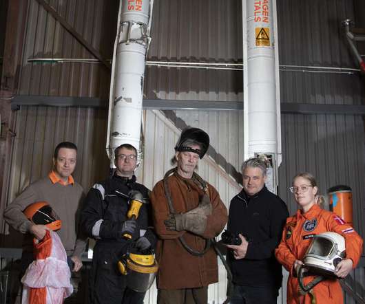
That successful mission in August 2018 was a huge step toward our goal of sending an amateur astronaut to the edge of space aboard one of our DIY rockets. The trickiest part, the double-curved "throat" section that connects the combustion chamber to the exhaust nozzle, requires computer-controlled machining equipment that we don't have.
I have had a DIY electric outboard boat motor in storage for a couple of years. I replaced the Curtis PB-8 throttle, checked that the connections were clean and correct and made sure the key switch was working but no luck.
I was able to reach the 3 motor connections from behind the driver side. But starting a week ago, as soon as we try to hit the pedal in either forward or reverse, we get an "003" error code. I'm looking to get a second opinion on what the upgrade company shared. They said it is a bad encoder or a loose wire on the motor.
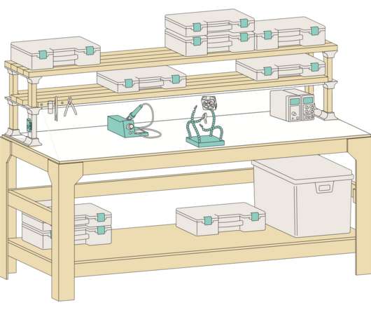
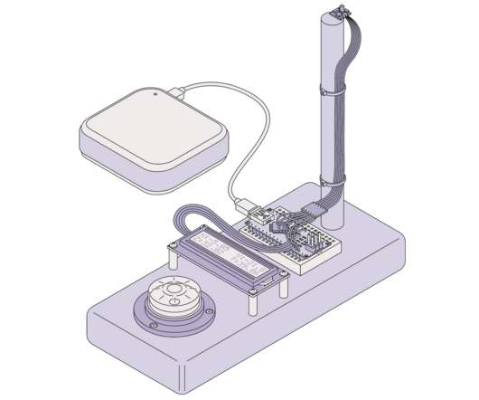
I added a DIY solder squid—a block with four flexible arms that I use to hold components in place while soldering—with a concrete base and an automatic solder fume extractor. The Grounduino provides screw terminals for hooking wires to the Nano and, as the name suggests, five extra ground connections (and five extra 5V connections as well).
I'm not fully certain what my DIY EV project is going to look like. But I find the connected nature of. I'm pretty mechanically savvy and spend a fair bit of time working on and modifying ICE cars, but I'm completely new to EVs.
What if four motors were used, with each motor mounted near the center (left to right) of the vehicle and a half shaft connecting the motor to the wheel? I know that hub motors have issues because of the sprung weight - especially a vehicle that will be traveling over rough terrain. The wheel would still be able to have a shock, etc.
The SavvyCan connection mode is: LAWICEL / SLCAN. git However, when I try the Orion BMS 2 utility “Connect To BMS” it only shows “Selected CANdapter None Found” Q1) Is this just some BS Orion/Ewert is doing to force the use of. Under Windows 10 I am able to successfully capture the Orion BMS canbus traffic in SavvyCan.
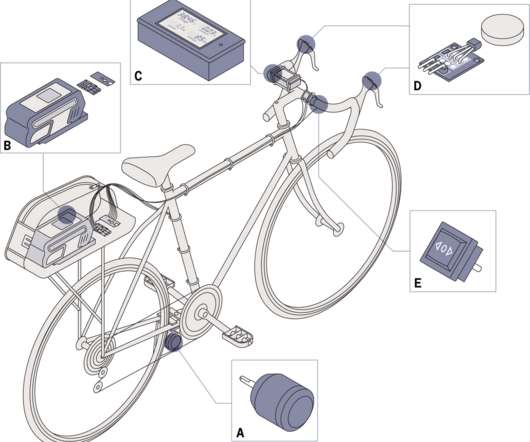
The handlebar-mounted controls connect with an Arduino, which interprets their settings and translates them into a PPM signal, which is applied to the electronic speed controller. The speed controller is connected to the motor and battery in the usual fashion, with an automotive-type blade fuse in line for safety.
Finally, after cajoling the machinist for a month, I finally got my connector between the motor and trans. I do have to hand it to Jon at Portland Manufacturing, he did a great job fabricating this connector it fit like a glove, and after assembling the motor and trans. It ran like a dream.
It has been suggested I connect to the OBD and record CANBUS data from my car and that from a car that has not been altered and feed. I have my 1965 Ford Falcon on the road with a 2021 Mustang Mach-e drive system (battery pack, rear motor/ suspension assembly, HVAC, ABS, on board charger , touch screen etc. ) I t runs and drives just great!
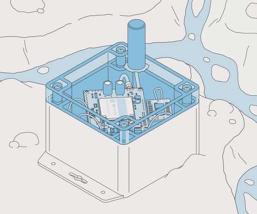
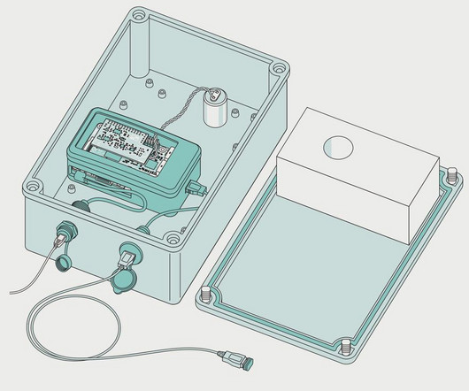
So, I set about building an open-source ice tracker from DIY components that not only proved to be much, much cheaper but also much more capable than the commercial options. With no guarantees on how long any given instrument might last, you have to deploy a lot of them to get the data you need.
It is likewise assumed to maximize the potential of connectivity features, meaning improved integration with artificial intelligence, advanced driving systems, and remote customization. Further integrating connectivity simultaneously opens up those vehicles to fresh vulnerabilities. The following may sound like science fiction.
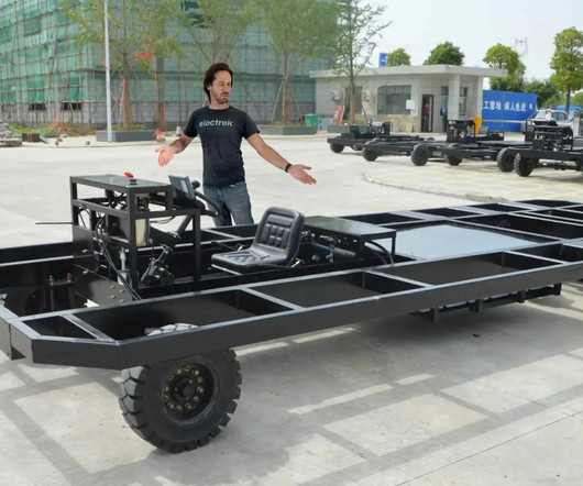
The motors, controllers, batteries, and everything else is usually built into a flat deck connected to the wheels, meaning the rest of the vehicle is basically just bolted on top. The engineer in me always thought it’d be fun to have just the bare skateboard, meaning you could go wild with your ideas of what to put on top.
Just about every device you own is probably available with Internet connectivity. needs Internet connectivity is up for debate. Connectivity usually comes at a premium, and it also usually involves buying a brand new whatever it is, because new hardware and software and services are required.
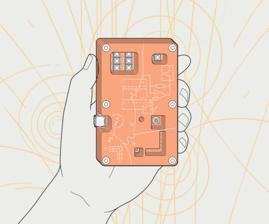
I connected this. I’ve not used my DIY magnetometer to search for any submarines or alien monoliths, but I did test it using a steel hammer, which affects the readings in an obvious way when placed within about a meter of the sensor board. This article appears in the May 2022 print issue as “A DIY Magnetometer.”.
But a totally acceptable result can be obtained by simply connecting all 4 hub motor drives to the same control signals. But a totally acceptable result can be obtained by simply connecting all 4 hub motor drives to the same control signals. You need a VCU to detect that and very very quickly turn of the other two. Click to expand.
Any advise of connecting the controller and how to run the key switch wiring and wiring from solenoid to battery? Seeking advice on setting up a Yamaha G14 E with an alltrax 400 controller? I would also prefer to do away with the lead acid charger port and wiring since it’s now 36V lithium. Thank you
These contain a TEF6686 chip in a DIY-friendly package, suitable for through-hole soldering (the TEF6686 itself is a surface-mounted chip), and with radio-frequency shielding to help minimize interference. I soon settled on a configuration consisting of two printed circuit boards connected by ribbon cable.
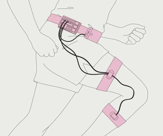
The IMUs are connected to a Raspberry Pi using the I2C protocol. The counter uses two of them, one attached at midthigh, the other at midshank. In our tests, we sometimes used toupee adhesive to hold various IMUs in place, but a Velcro strap works great, too!
I can connect and read/change config settings fine. But the same cable/software won't connect to the 1253-8001. Hi, I have 2 controllers, I need to get the 1253-8001 working for my conversion build. I created a frankenstein serial cable and it works fine with the 1205M-5601. Any ideas? I'm scratching my head here.
The handlebar-mounted controls connect with an Arduino, which interprets their settings and translates them into a PPM signal, which is applied to the electronic speed controller. The speed controller is connected to the motor and battery in the usual fashion, with an automotive-type blade fuse in line for safety.
So directly connecting the leaf motor to the transmission input is a no-go. Hi all I'm in the early stages of putting a Leaf motor (EM57) into a 93 Subaru Sambar. Or I was, it turns out the leaf motor is too wide and would intersect with the rear right half shaft by about an inch.
The purple key switch wire 1 (KSI) is connected to B+ in the below diagram via a switch. Hi I need urgent advice for the correct wiring of a Enpower 3336 controller hooked up to a nominal 96 volt battery pack. My question! Is that B+ wire going to 1 (KSI) from the B+ positive 96 volt terminal on the contoller?
And we intend to stimulate and grow new connections - a whole lot of them. In addition to Creative Greenius you’ll find these great EV Driven blogs: DIY Electric Car. We have come together to find and organize the best content from blogs and other web sites. Starting right now. Electric Car Blog. Electric Cars are for Girls.
Fortunately, certain maintenance tasks are DIY projects and can save you money, as the average cost of car repairs ranges between $300 to $500. This article highlights some DIY car maintenance tasks you can tackle at home. Straight-end connection wipers require a screwdriver to depress a tab within the arm.
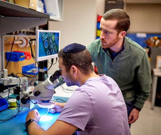
Oliver Keller at CERN’s S’Cool Lab has created a DIY particle detector that relies on inexpensive silicon photodiodes to detect alpha and beta particles (helium nuclei and free electrons whizzing through the air, respectively) and estimate their energy. I’m doing a Ph.D. Fortunately, I didn’t have to start from scratch.
Now, after countless versions of wiring things together, and even designing my own audio mixers, I finally have a DIY solution that works within a reasonable budget. I chose the $10 ESP32 because it would allow me to operate the WM8960 and also accept audio via a Bluetooth connection from, say, my phone, and stream it to the WM8960.
Searching the interwebs, I found no shortage of leads about how to build a DIY seismometer. The problem is that the DIY seismometer designs I was seeing were large and ungainly contraptions. I investigated what some other Web-connected Raspberry Shakes had recorded during that earthquake.
I thought the engine/tranny was connected to the frame with three engine mounts, two bolts on the side and one connection in front. After removing these three connections I started to lift. I looked under the car (again) and noticed that the tranny seems connected to the underside. Something didn't feel right.
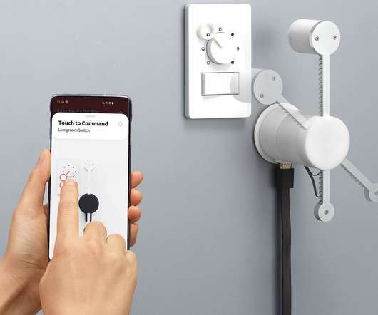
It’s nearly impossible to find a household today that doesn’t have at least one connected smart home device installed. It redefined the home security space by introducing wireless, DIY products and pioneered giving customers the ability to monitor their homes via a smartphone app. SimpliSafe works differently.
I was wondering if anyone had any luck connecting their motor controller to CAN through arduino. Hey guys, I am an newbie when it comes to motor controllers. I'm currently in the design phase so I have yet to actual get my hands on the parts. If anyone has any advice with CAN, please let me know.
Connected the traction cables and charger cables to the bus bar and enclosed it in an electrical box. Connected traction fuse, in separate electrical box near the pack. Connected charger cables to bus bar via waterproof plug (not necessary for the bench test). Connected the rows together.
The only thing left connecting the engine to the car were the engine bolts. We connected the lift, removed the engine bolts (holding the engine from the frame) and started to lift. We (Stu and I) disconnected the axle from the outer CV joint (basically disconnected the axle from the wheel).
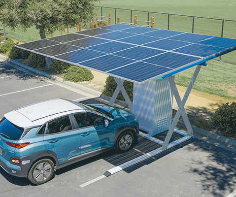
The Simple Installation Process For small solar setups oriented towards sheds, DIY installation kits can streamline the process: – Position the Panel: Orient the solar panels to maximize sun exposure based on your hemisphere. . – Thin-Film: The most flexible solar panel option, but has marginally reduced efficiency levels.
There are also videos on Youtube where people change the pack the DIY way or the individual modules, but be aware to only buy individual modules from a trusted source. One of our 2006 Prius’ pack needed servicing and it only cost a few hundred dollars to fix 7 modules and change the bus bars connecting the modules by a hybrid shop.
We organize all of the trending information in your field so you don't have to. Join 5,000+ users and stay up to date on the latest articles your peers are reading.
You know about us, now we want to get to know you!
Let's personalize your content
Let's get even more personalized
We recognize your account from another site in our network, please click 'Send Email' below to continue with verifying your account and setting a password.


Let's personalize your content