The Conversation (1)

The Kapaia solar-plus-storage facility, operated by the Kauai Island Utility Cooperative, includes 52 megawatt-hours of energy storage. The storage is based on Tesla’s Powerpack 2 battery system.
TESLA
DarkBlue2
It’s late in the afternoon of 2 April 2023 on the island of Kauai. The sun is sinking over this beautiful and peaceful place, when, suddenly, at 4:25 pm, there’s a glitch: The largest generator on the island, a 26-megawatt oil-fired turbine, goes offline.
This is a more urgent problem than it might sound. The westernmost Hawaiian island of significant size, Kauai is home to around 70,000 residents and 30,000 tourists at any given time. Renewable energy accounts for 70 percent of the energy produced in a typical year—a proportion that’s among the highest in the world and that can be hard to sustain for such a small and isolated grid. During the day, the local system operator, the Kauai Island Utility Cooperative, sometimes reaches levels of 90 percent from solar alone. But on 2 April, the 26-MW generator was running near its peak output, to compensate for the drop in solar output as the sun set. At the moment when it failed, that single generator had been supplying 60 percent of the load for the entire island, with the rest being met by a mix of smaller generators and several utility-scale solar-and-battery systems.
Normally, such a sudden loss would spell disaster for a small, islanded grid. But the Kauai grid has a feature that many larger grids lack: a technology called grid-forming inverters. An inverter converts direct-current electricity to grid-compatible alternating current. The island’s grid-forming inverters are connected to those battery systems, and they are a special type—in fact, they had been installed with just such a contingency in mind. They improve the grid’s resilience and allow it to operate largely on resources like batteries, solar photovoltaics, and wind turbines, all of which connect to the grid through inverters. On that April day in 2023, Kauai had over 150 megawatt-hours’ worth of energy stored in batteries—and also the grid-forming inverters necessary to let those batteries respond rapidly and provide stable power to the grid. They worked exactly as intended and kept the grid going without any blackouts.
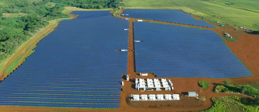 The photovoltaic panels at the Kapaia solar-plus-storage facility, operated by the Kauai Island Utility Cooperative in Hawaii, are capable of generating 13 megawatts under ideal conditions.TESLA
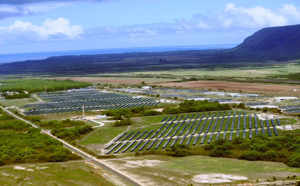 A solar-plus-storage facility at the U.S. Navy’s Pacific Missile Range Facility, in the southwestern part of Kauai, is one of two on the island equipped with grid-forming inverters. U.S. NAVY
That April event in Kauai offers a preview of the electrical future, especially for places where utilities are now, or soon will be, relying heavily on solar photovoltaic or wind power. Similar inverters have operated for years within smaller off-grid installations. However, using them in a multimegawatt power grid, such as Kauai’s, is a relatively new idea. And it’s catching on fast: At the time of this writing, at least eight major grid-forming projects are either under construction or in operation in Australia, along with others in Asia, Europe, North America, and the Middle East.
Reaching net-zero-carbon emissions by 2050, as many international organizations now insist is necessary to stave off dire climate consequences, will require a rapid and massive shift in electricity-generating infrastructures. The International Energy Agency has calculated that to have any hope of achieving this goal would require the addition, every year, of 630 gigawatts of solar photovoltaics and 390 GW of wind starting no later than 2030—figures that are around four times as great as than any annual tally so far.
The only economical way to integrate such high levels of renewable energy into our grids is with grid-forming inverters, which can be implemented on any technology that uses an inverter, including wind, solar photovoltaics, batteries, fuel cells, microturbines, and even high-voltage direct-current transmission lines. Grid-forming inverters for utility-scale batteries are available today from Tesla, GPTech, SMA, GE Vernova, EPC Power, Dynapower, Hitachi, Enphase, CE+T, and others. Grid-forming converters for HVDC, which convert high-voltage direct current to alternating current and vice versa, are also commercially available, from companies including Hitachi, Siemens, and GE Vernova. For photovoltaics and wind, grid-forming inverters are not yet commercially available at the size and scale needed for large grids, but they are now being developed by GE Vernova, Enphase, and Solectria.
The Grid Depends on Inertia
To understand the promise of grid-forming inverters, you must first grasp how our present electrical grid functions, and why it’s inadequate for a future dominated by renewable resources such as solar and wind power.
Conventional power plants that run on natural gas, coal, nuclear fuel, or hydropower produce electricity with synchronous generators—large rotating machines that produce AC electricity at a specified frequency and voltage. These generators have some physical characteristics that make them ideal for operating power grids. Among other things, they have a natural tendency to synchronize with one another, which helps make it possible to restart a grid that’s completely blacked out. Most important, a generator has a large rotating mass, namely its rotor. When a synchronous generator is spinning, its rotor, which can weigh well over 100 tonnes, cannot stop quickly.
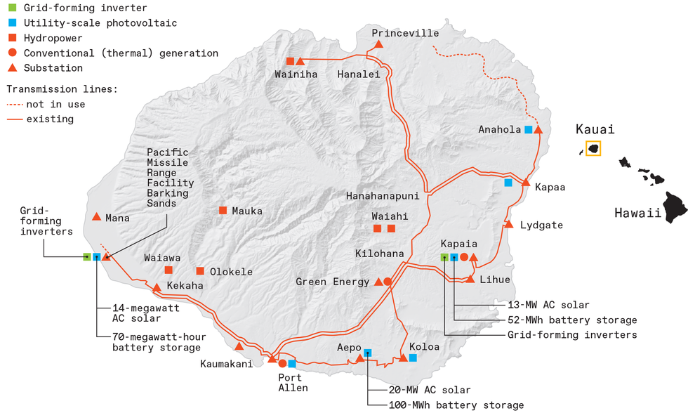 The Kauai electric transmission grid operates at 57.1 kilovolts, an unusual voltage that is a legacy from the island’s sugar-plantation era. The network has grid-forming inverters at the Pacific Missile Range Facility, in the southwest, and at Kapaia, in the southeast. CHRIS PHILPOT
This characteristic gives rise to a property called system inertia. It arises naturally from those large generators running in synchrony with one another. Over many years, engineers used the inertia characteristics of the grid to determine how fast a power grid will change its frequency when a failure occurs, and then developed mitigation procedures based on that information.
If one or more big generators disconnect from the grid, the sudden imbalance of load to generation creates torque that extracts rotational energy from the remaining synchronous machines, slowing them down and thereby reducing the grid frequency—the frequency is electromechanically linked to the rotational speed of the generators feeding the grid. Fortunately, the kinetic energy stored in all that rotating mass slows this frequency drop and typically allows the remaining generators enough time to ramp up their power output to meet the additional load.
Electricity grids are designed so that even if the network loses its largest generator, running at full output, the other generators can pick up the additional load and the frequency nadir never falls below a specific threshold. In the United States, where nominal grid frequency is 60 hertz, the threshold is generally between 59.3 and 59.5 Hz. As long as the frequency remains above this point, local blackouts are unlikely to occur.
Why We Need Grid-Forming Inverters
Wind turbines, photovoltaics, and battery-storage systems differ from conventional generators because they all produce direct current (DC) electricity—they don’t have a heartbeat like alternating current does. With the exception of wind turbines, these are not rotating machines. And most modern wind turbines aren’t synchronously rotating machines from a grid standpoint—the frequency of their AC output depends on the wind speed. So that variable-frequency AC is rectified to DC before being converted to an AC waveform that matches the grid’s.
As mentioned, inverters convert the DC electricity to grid-compatible AC. A conventional, or grid-following, inverter uses power transistors that repeatedly and rapidly switch the polarity applied to a load. By switching at high speed, under software control, the inverter produces a high-frequency AC signal that is filtered by capacitors and other components to produce a smooth AC current output. So in this scheme, the software shapes the output waveform. In contrast, with synchronous generators the output waveform is determined by the physical and electrical characteristics of the generator.
Grid-following inverters operate only if they can “see” an existing voltage and frequency on the grid that they can synchronize to. They rely on controls that sense the frequency of the voltage waveform and lock onto that signal, usually by means of a technology called a phase-locked loop. So if the grid goes down, these inverters will stop injecting power because there is no voltage to follow. A key point here is that grid-following inverters do not deliver any inertia.
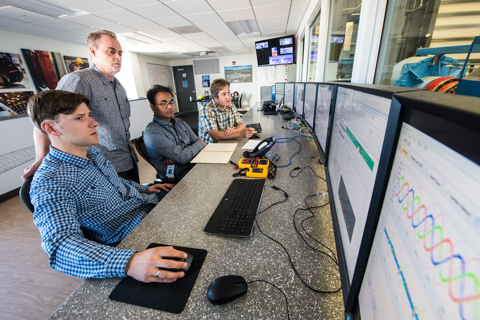 Przemyslaw Koralewicz, David Corbus, Shahil Shah, and Robb Wallen, researchers at the National Renewable Energy Laboratory, evaluate a grid-forming inverter used on Kauai at the NREL Flatirons Campus. DENNIS SCHROEDER/NREL
Grid-following inverters work fine when inverter-based power sources are relatively scarce. But as the levels of inverter-based resources rise above 60 to 70 percent, things start to get challenging. That’s why system operators around the world are beginning to put the brakes on renewable deployment and curtailing the operation of existing renewable plants. For example, the Electric Reliability Council of Texas (ERCOT) regularly curtails the use of renewables in that state because of stability issues arising from too many grid-following inverters.
It doesn’t have to be this way. When the level of inverter-based power sources on a grid is high, the inverters themselves could support grid-frequency stability. And when the level is very high, they could form the voltage and frequency of the grid. In other words, they could collectively set the pulse, rather than follow it. That’s what grid-forming inverters do.
The Difference Between Grid Forming and Grid Following
Grid-forming (GFM) and grid-following (GFL) inverters share several key characteristics. Both can inject current into the grid during a disturbance. Also, both types of inverters can support the voltage on a grid by controlling their reactive power, which is the product of the voltage and the current that are out of phase with each other. Both kinds of inverters can also help prop up the frequency on the grid, by controlling their active power, which is the product of the voltage and current that are in phase with each other.
What makes grid-forming inverters different from grid-following inverters is mainly software. GFM inverters are controlled by code designed to maintain a stable output voltage waveform, but they also allow the magnitude and phase of that waveform to change over time. What does that mean in practice? The unifying characteristic of all GFM inverters is that they hold a constant voltage magnitude and frequency on short timescales—for example, a few dozen milliseconds—while allowing that waveform’s magnitude and frequency to change over several seconds to synchronize with other nearby sources, such as traditional generators and other GFM inverters.
Some GFM inverters, called virtual synchronous machines, achieve this response by mimicking the physical and electrical characteristics of a synchronous generator, using control equations that describe how it operates. Other GFM inverters are programmed to simply hold a constant target voltage and frequency, allowing that target voltage and frequency to change slowly over time to synchronize with the rest of the power grid following what is called a droop curve. A droop curve is a formula used by grid operators to indicate how a generator should respond to a deviation from nominal voltage or frequency on its grid. There are many variations of these two basic GFM control methods, and other methods have been proposed as well.
At least eight major grid-forming projects are eitherunder construction or in operation in Australia, along with others in Asia, Europe, North America, and the Middle East.
To better understand this concept, imagine that a transmission line shorts to ground or a generator trips due to a lightning strike. (Such problems typically occur multiple times a week, even on the best-run grids.) The key advantage of a GFM inverter in such a situation is that it does not need to quickly sense frequency and voltage decline on the grid to respond. Instead, a GFM inverter just holds its own voltage and frequency relatively constant by injecting whatever current is needed to achieve that, subject to its physical limits. In other words, a GFM inverter is programmed to act like an AC voltage source behind some small impedance (impedance is the opposition to AC current arising from resistance, capacitance, and inductance). In response to an abrupt drop in grid voltage, its digital controller increases current output by allowing more current to pass through its power transistors, without even needing to measure the change it’s responding to. In response to falling grid frequency, the controller increases power.
GFL controls, on the other hand, need to first measure the change in voltage or frequency, and then take an appropriate control action before adjusting their output current to mitigate the change. This GFL strategy works if the response does not need to be superfast (as in microseconds). But as the grid becomes weaker (meaning there are fewer voltage sources nearby), GFL controls tend to become unstable. That’s because by the time they measure the voltage and adjust their output, the voltage has already changed significantly, and fast injection of current at that point can potentially lead to a dangerous positive feedback loop. Adding more GFL inverters also tends to reduce stability because it becomes more difficult for the remaining voltage sources to stabilize them all.
When a GFM inverter responds with a surge in current, it must do so within tightly prescribed limits. It must inject enough current to provide some stability but not enough to damage the power transistors that control the current flow.
Increasing the maximum current flow is possible, but it requires increasing the capacity of the power transistors and other components, which can significantly increase cost. So most inverters (both GFM and GFL) don’t provide current surges larger than about 10 to 30 percent above their rated steady-state current. For comparison, a synchronous generator can inject around 500 to 700 percent more than its rated current for several AC line cycles (around a tenth of a second, say) without sustaining any damage. For a large generator, this can amount to thousands of amperes. Because of this difference between inverters and synchronous generators, the protection technologies used in power grids will need to be adjusted to account for lower levels of fault current.
What the Kauai Episode Reveals
The 2 April event on Kauai offered an unusual opportunity to study the performance of GFM inverters during a disturbance. After the event, one of us (Andy Hoke) along with Jin Tan and Shuan Dong and some coworkers at the National Renewable Energy Laboratory, collaborated with the Kauai Island Utility Cooperative (KIUC) to get a clear understanding of how the remaining system generators and inverter-based resources interacted with each other during the disturbance. What we determined will help power grids of the future operate at levels of inverter-based resources up to 100 percent.
NREL researchers started by creating a model of the Kauai grid. We then used a technique called electromagnetic transient (EMT) simulation, which yields information on the AC waveforms on a sub-millisecond basis. In addition, we conducted hardware tests at NREL’s Flatirons Campus on a scaled-down replica of one of Kauai’s solar-battery plants, to evaluate the grid-forming control algorithms for inverters deployed on the island.The leap from power systems like Kauai’s, with a peak demand of roughly 80 MW, to ones like South Australia’s, at 3,000 MW, is a big one. But it’s nothing compared to what will come next: grids with peak demands of 85,000 MW (in Texas) and 742,000 MW (the rest of the continental United States).
Several challenges need to be solved before we can attempt such leaps. They include creating standard GFM specifications so that inverter vendors can create products. We also need accurate models that can be used to simulate the performance of GFM inverters, so we can understand their impact on the grid.
Some progress in standardization is already happening. In the United States, for example, the North American Electric Reliability Corporation (NERC) recently published a recommendation that all future large-scale battery-storage systems have grid-forming capability.
Standards for GFM performance and validation are also starting to emerge in some countries, including Australia, Finland, and Great Britain. In the United States, the Department of Energy recently backed a consortium to tackle building and integrating inverter-based resources into power grids. Led by the National Renewable Energy Laboratory, the University of Texas at Austin, and the Electric Power Research Institute, the Universal Interoperability for Grid-Forming Inverters (UNIFI) Consortium aims to address the fundamental challenges in integrating very high levels of inverter-based resources with synchronous generators in power grids. The consortium now has over 30 members from industry, academia, and research laboratories.
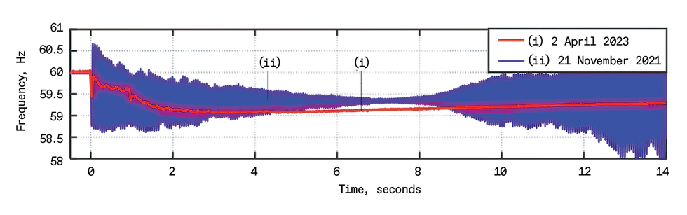 A recording of the frequency responses to two different grid disruptions on Kauai shows the advantages of grid-forming inverters. The red trace shows the relatively contained response with two grid-forming inverter systems in operation. The blue trace shows the more extreme response to an earlier, comparable disruption, at a time when there was only one grid-forming plant online.NATIONAL RENEWABLE ENERGY LABORATORY
At 4:25 pm on 2 April, there were two large GFM solar-battery plants, one large GFL solar-battery plant, one large oil-fired turbine, one small diesel plant, two small hydro plants, one small biomass plant, and a handful of other solar generators online. Immediately after the oil-fired turbine failed, the AC frequency dropped quickly from 60 Hz to just above 59 Hz during the first 3 seconds [red trace in the figure above]. As the frequency dropped, the two GFM-equipped plants quickly ramped up power, with one plant quadrupling its output and the other doubling its output in less than 1/20 of a second.
In contrast, the remaining synchronous machines contributed some rapid but unsustained active power via their inertial responses, but took several seconds to produce sustained increases in their output. It is safe to say, and it has been confirmed through EMT simulation, that without the two GFM plants, the entire grid would have experienced a blackout.
Coincidentally, an almost identical generator failure had occurred a couple of years earlier, on 21 November 2021. In this case, only one solar-battery plant had grid-forming inverters. As in the 2023 event, the three large solar-battery plants quickly ramped up power and prevented a blackout. However, the frequency and voltage throughout the grid began to oscillate around 20 times per second [the blue trace in the figure above], indicating a major grid stability problem and causing some customers to be automatically disconnected. NREL’s EMT simulations, hardware tests, and controls analysis all confirmed that the severe oscillation was due to a combination of grid-following inverters tuned for extremely fast response and a lack of sufficient grid strength to support those GFL inverters.
In other words, the 2021 event illustrates how too many conventional GFL inverters can erode stability. Comparing the two events demonstrates the value of GFM inverter controls—not just to provide fast yet stable responses to grid events but also to stabilize nearby GFL inverters and allow the entire grid to maintain operations without a blackout.
Australia Commissions Big GFM Projects
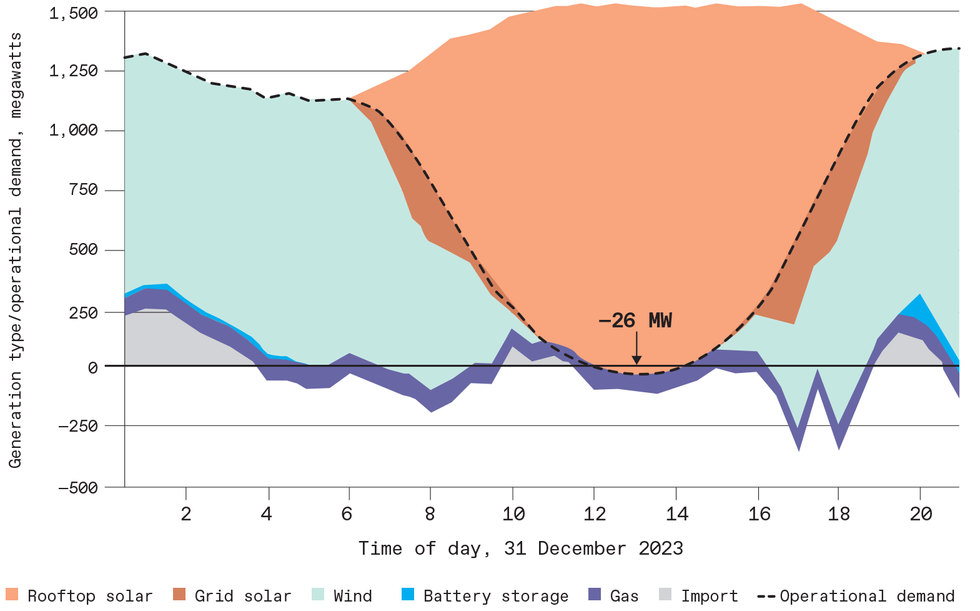 In sunny South Australia, solar power now routinely supplies all or nearly all of the power needed during the middle of the day. Shown here is the chart for 31 December 2023, in which solar supplied slightly more power than the state needed at around 1:30 p.m. AUSTRALIAN ENERGY MARKET OPERATOR (AEMO)
The next step for inverter-dominated power grids is to go big. Some of the most important deployments are in South Australia. As in Kauai, the South Australian grid now has such high levels of solar generation that it regularly experiences days in which the solar generation can exceed the peak demand during the middle of the day [see figure at left].
The most well-known of the GFM resources in Australia is the Hornsdale Power Reserve in South Australia. This 150-MW/194-MWh system, which uses Tesla’s Powerpack 2 lithium-ion batteries, was originally installed in 2017 and was upgraded to grid-forming capability in 2020.
Australia’s largest battery (500 MW/1,000 MWh) with grid-forming inverters is expected to start operating in Liddell, New South Wales, later this year. This battery, from AGL Energy, will be located at the site of a decommissioned coal plant. This and several other larger GFM systems are expected to start working on the South Australia grid over the next year.
The leap from power systems like Kauai’s, with a peak demand of roughly 80 MW, to ones like South Australia’s, at 3,000 MW, is a big one. But it’s nothing compared to what will come next: grids with peak demands of 85,000 MW (in Texas) and 742,000 MW (the rest of the continental United States).
Several challenges need to be solved before we can attempt such leaps. They include creating standard GFM specifications so that inverter vendors can create products. We also need accurate models that can be used to simulate the performance of GFM inverters, so we can understand their impact on the grid.
Some progress in standardization is already happening. In the United States, for example, the North American Electric Reliability Corporation (NERC) recently published a recommendation that all future large-scale battery-storage systems have grid-forming capability.
Standards for GFM performance and validation are also starting to emerge in some countries, including Australia, Finland, and Great Britain. In the United States, the Department of Energy recently backed a consortium to tackle building and integrating inverter-based resources into power grids. Led by the National Renewable Energy Laboratory, the University of Texas at Austin, and the Electric Power Research Institute, the Universal Interoperability for Grid-Forming Inverters (UNIFI) Consortium aims to address the fundamental challenges in integrating very high levels of inverter-based resources with synchronous generators in power grids. The consortium now has over 30 members from industry, academia, and research laboratories.
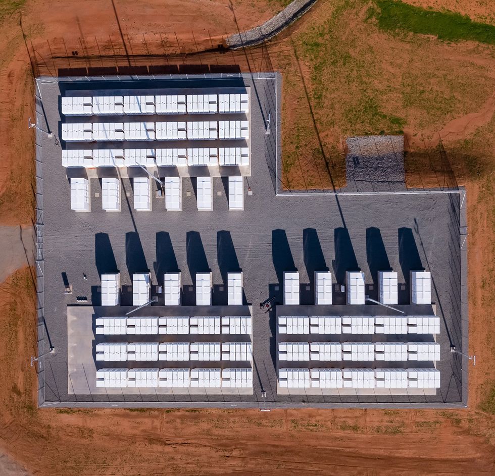 One of Australia’s major energy-storage facilities is the Hornsdale Power Reserve, at 150 megawatts and 194 megawatt-hours. Hornsdale, along with another facility called the Riverina Battery, are the country’s two largest grid-forming installations. NEOEN
In addition to specifications, we need computer models of GFM inverters to verify their performance in large-scale systems. Without such verification, grid operators won’t trust the performance of new GFM technologies. Using GFM models built by the UNIFI Consortium, system operators and utilities such as the Western Electricity Coordinating Council, American Electric Power, and ERCOT (the Texas’s grid-reliability organization) are conducting studies to understand how GFM technology can help their grids.
Getting to a Greener Grid
As we progress toward a future grid dominated by inverter-based generation, a question naturally arises: Will all inverters need to be grid-forming? No. Several studies and simulations have indicated that we’ll need just enough GFM inverters to strengthen each area of the grid so that nearby GFL inverters remain stable.
How many GFMs is that? The answer depends on the characteristics of the grid and other generators. Some initial studies have shown that a power system can operate with 100 percent inverter-based resources if around 30 percent are grid-forming. More research is needed to understand how that number depends on details such as the grid topology and the control details of both the GFLs and the GFMs.
Ultimately, though, electricity generation that is completely carbon free in its operation is within our grasp. Our challenge now is to make the leap from small to large to very large systems. We know what we have to do, and it will not require technologies that are far more advanced than what we already have. It will take testing, validation in real-world scenarios, and standardization so that synchronous generators and inverters can unify their operations to create a reliable and robust power grid. Manufacturers, utilities, and regulators will have to work together to make this happen rapidly and smoothly. Only then can we begin the next stage of the grid’s evolution, to large-scale systems that are truly carbon neutral.
This article appears in the May 2024 print issue as “A Path to 100 Percent Renewable Energy.”
{"imageShortcodeIds":[]}


