Sponsored by Littelfuse.
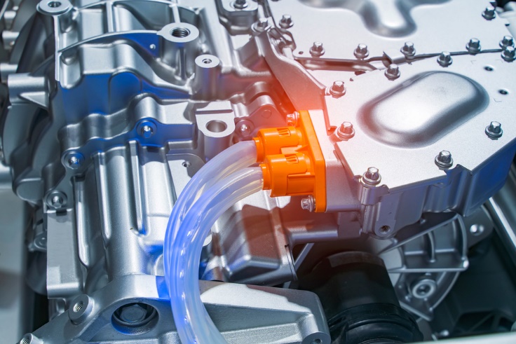
The automotive environment is one of the most severe environments for electronics. Today’s vehicle designs proliferate with sensitive electronics, including electronic controls, infotainment, sensing, battery packs, battery management, electric vehicle powertrains, and on-board chargers. In addition to the heat, voltage transients, and electromagnetic interference (EMI) in the automotive environment, the on-board charger must interface with the AC power grid, requiring protection from AC line disturbances for reliable operation.
Today’s component manufacturers offer multiple devices for safeguarding electronic circuits. Due to the connection to the grid, on-board charger protection from voltage surges using unique components is essential.
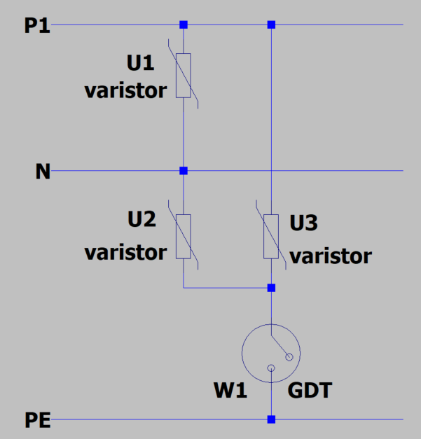
Littelfuse solutions focus on advanced overcurrent and overvoltage protection technologies, including MOV (Metal Oxide Varistor), TVS (Transient Voltage Suppressor), GDT (Gas Discharge Tube), and SIDACtor® protection thyristors. The challenge for design engineers? How to optimize the component selection and determine the best combination of technologies to reach the best performance and price.
A unique solution combines a SIDACtor and a Varistor (SMD or THT), reaching a low clamping voltage under a high surge pulse. The SIDACtor+MOV combination enables automotive engineers to optimize the selection and, therefore, the cost of the power semiconductors in the design. These parts are needed to convert the AC voltage into the DC voltage to charge the vehicle’s on-board battery.
The On-Board Charger (OBC) is at risk during EV charging due to exposure to overvoltage events that may occur on the power grid. The design must protect the power semiconductors from overvoltage transients because voltages above their maximum limits can damage them. To extend the EV’s reliability and lifetime, engineers must address increasing surge current requirements and lower maximum clamping voltage in their designs.
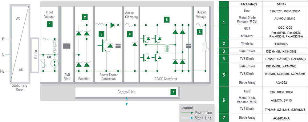
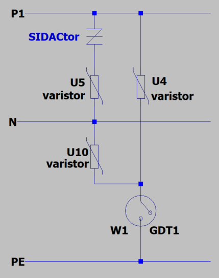
Figure 1 shows the circuits requiring protection components and blocks that can employ high-efficiency components. The table lists the recommended technologies.
The potential surge pulses for the OBC come from indirect lightning strikes, load switching, and failure in the system. Imagine the power of a direct lightning strike of 100kA; a high surge current requirement in the specification is understandable. Other possible root causes for a surge pulse are abrupt load switching and faults in the power system.
Example sources of transient voltage surges include the following:
- Switching of capacitive loads
- Switching of low voltage systems and resonant circuits
- Short circuits resulting from construction, traffic accidents, or storms
- Triggered fuses and overvoltage protection.
The coupling of the surge pulses is capacitive on parallel cables, inductive on conductor loops, and emission in the near field. The transient surge occurs over cable (on power, data, or signal lines), and it can be symmetrical (line-to-line) or asymmetrical (line-to-ground). It is crucial to know the coupling and propagation source to solve the application problem.
The IEC-61000-4-5 is the relevant standard for surge immunity. Table 1 lists maximum surge voltages up to 4kV. The 2Ω generator resistance results in a 2kA surge pulse (1a). The IEEE C62.41.2-2002 standard specifies a 6 kV/3 kA surge rating (1b). Today, most power grid-related AC power circuits are designed to resist the IEEE surge requirement.
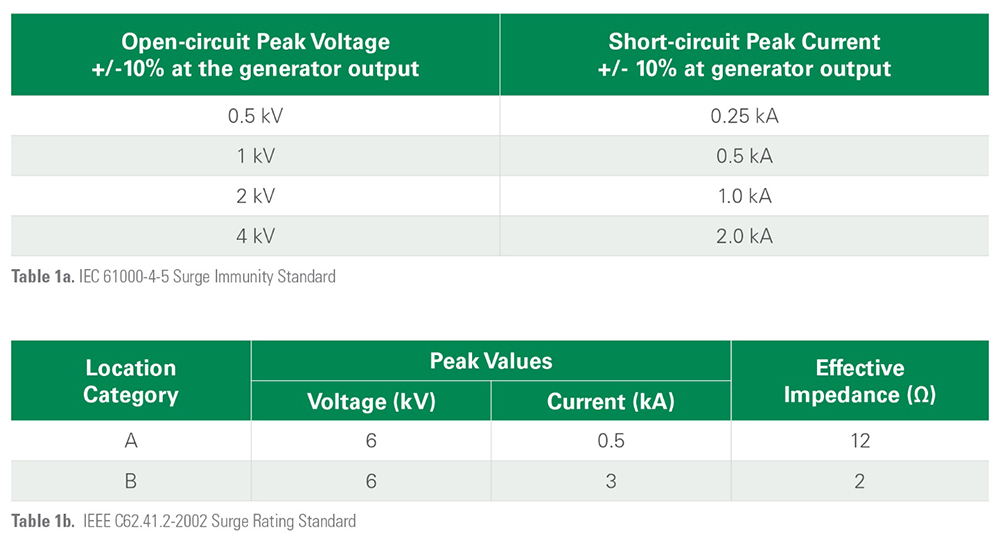
IEEE C62.41.2-2002 Standard 1.2/50 µs-8/20 µs, expected voltages and current surges.
According to the 6kV/3kA surge, many designers use 14mm MOVs in the AC primary side circuit.
A 20mm MOV is preferred for better reliability and protection. The 20mm MOV handles 45 pulses of 6kV/3kA surge current, which is much more robust than the 14mm MOV. The 14mm disc can only handle around 14 surges over its lifetime.
Voltage transient protection performance comparison
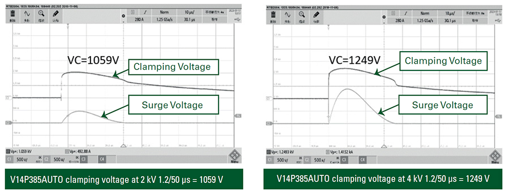
Compare an MOV’s transient voltage protection performance with a SIDACtor+MOV combination. Figure 3 shows the clamping performance of a 14mm MOV when struck with a 2kV and a 4kV surge. The MOV has a maximum operating voltage of 385VACRMS. The clamping voltages are more than 1000V, which puts a high stress level on the power semiconductors.
MOV transient voltage performance
MOV Selection Parameters
- Rated Operating Voltage—Maximum continuous voltage of the circuit to be protected.
- Ambient Temperature—Temperature in the area surrounding the MOV, used to determine if thermal derating is needed.
- Transient Voltage Waveform—Defines the transient pulse, including peak voltage, duration, and transient source impedance, typically provided in a Standard (e.g., IEC-61000-4-5).
- Quantity of Transient Voltage Pulses—Defined by the Standard, this is the number of pulses that the components must survive, and that the MOV will need to absorb.
- Peak Pulse Current–Transient voltage pulse and the generator’s internal resistance provide the peak current.
- Mounting requirements of MOV (straight, bent leads or SMD).
- Requirement to meet the 6kV/3kA waveform drives MOV selection. The typical lifetime requirement is 10 pulses.
Example selection determination
Level 1 Charger—120VAC, single-phase circuit: The expected ambient temperature is 100°C.
Step 1: Determine the minimum voltage rating of the MOV. The rule of thumb is to add 25% to the nominal AC line voltage to account for an imperfect power service: 120VAC x 1.25 = 150VAC. This is the minimum suggested voltage rating. The maximum peak surge current must be above 3kA.
Step 2: Repetitive Surge Capability must meet the standard requirements. The peak surge current and the energy rating must be reduced based on the temperature derating chart. The high potential capacity depends on the coating selection. Using a GDT helps the protection configuration achieve the leakage requirements of the High Potential test, which an MOV cannot meet alone.
SIDACtor+MOV transient voltage performance
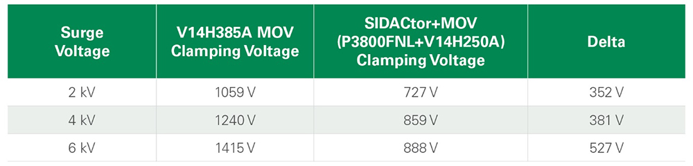
The SIDACtor+MOV approach has several advantages. The primary benefit is that for a 6KV/3KA surge, the clamping voltage is under 1000V as indicated in Table 2.
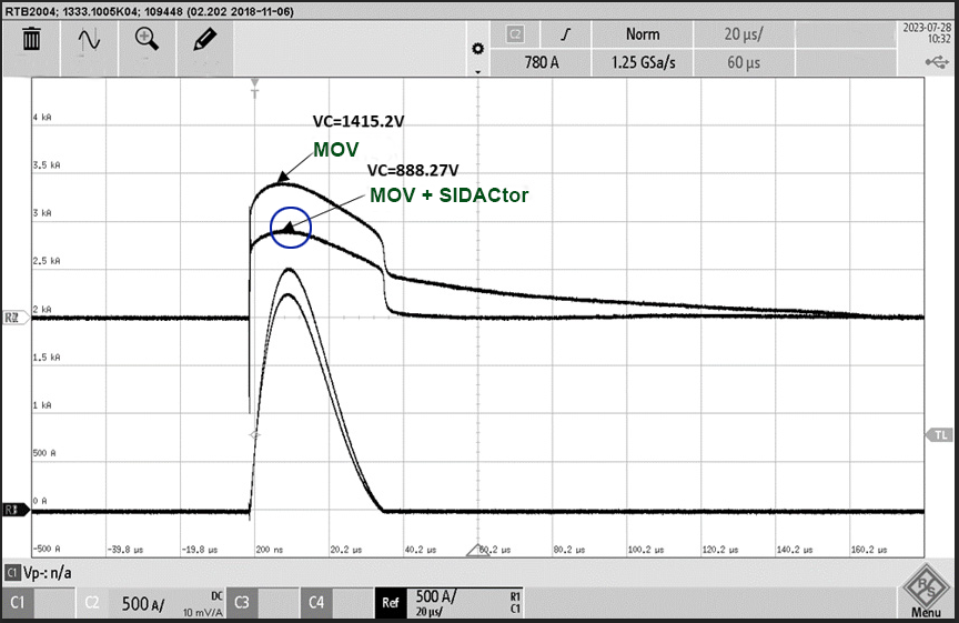
Figure 5 illustrates the voltage versus time response of the MOV and SIDACtor+MOV combination, again showing that the SIDACtor+MOV combination has a lower clamping voltage.
An MOV alone shows degeneration after multiple surges. The leakage current increases with the number of surges the MOV must absorb. Also, the breakdown voltage is expected to fall with an increasing number of surge strikes. The rising leakage and the clamping voltage change show the MOV parameters’ drift. Designer should select a larger disc size to avoid this situation with an MOV. This approach impacts the cost and consumes critical PCB space. However, their performance is more stable with a SIDACtor+MOV combination, and the SIDACtor extends the MOV lifetime.
SIDACtor+MOV: The superior solution for transient surge protection
While a designer will consider an MOV for voltage transient protection of downstream circuitry, Littelfuse can offer the designer a superior solution with its SIDACtor protection thyristor placed in series with an MOV. The SIDACtor+MOV combination has a lower clamping voltage to reduce semiconductor stress. In addition, the combination has a much lower leakage current and a breakdown voltage that degrades much less with increasing transient strikes. Using a SIDACtor+MOV combination for transient surge protection will result in a more reliable, robust on-board charger.
To learn more about using SIDACtor Protection Thyristors in electric vehicles, download the full application note How to Select the Optimum Transient Surge Protection for EV On-Board Chargers, courtesy of TTI and Littelfuse, Inc.