
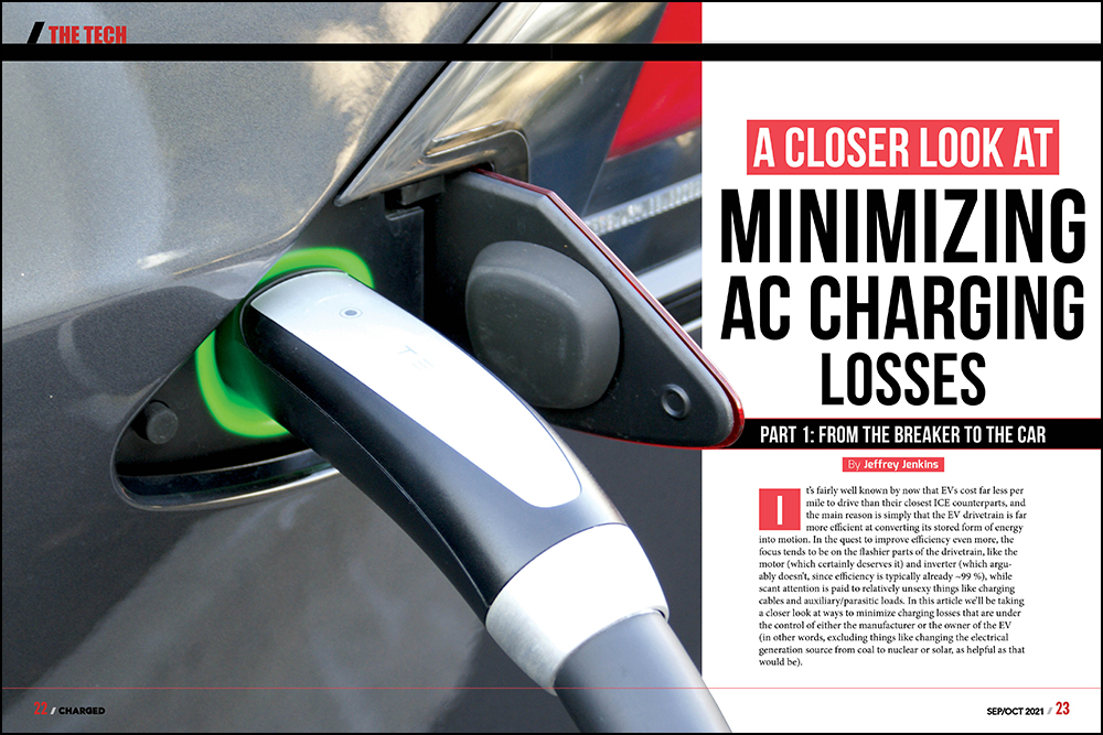
It’s fairly well known by now that EVs cost far less per mile to drive than their closest ICE counterparts, and the main reason is simply that the EV drivetrain is far more efficient at converting its stored form of energy into motion. In the quest to improve efficiency even more, the focus tends to be on the flashier parts of the drivetrain, like the motor (which certainly deserves it) and inverter (which arguably doesn’t, since efficiency is typically already ~99 %), while scant attention is paid to relatively unsexy things like charging cables and auxiliary/parasitic loads. In this article we’ll be taking a closer look at ways to minimize charging losses that are under the control of either the manufacturer or the owner of the EV (in other words, excluding things like changing the electrical generation source from coal to nuclear or solar, as helpful as that would be).
First, in the interest of clarity, let’s define some terms that we’ll use in this article.
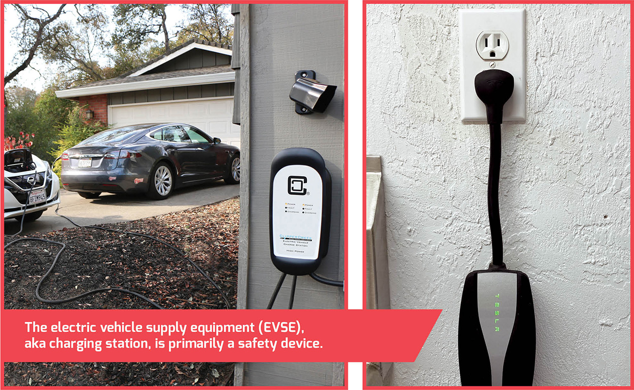
EVSE: The electric vehicle supply equipment, also known as a Level 1 or Level 2 charging station or charger. These include portable charging cord sets (aka trunk chargers), and larger wall-mounted or pedestal-mounted units.
The basic function of the EVSE is to provide redundant safety features to protect the user from electrical hazards while connecting and disconnecting the plug to the vehicle.
OBC: The onboard charger, a piece of power electronics equipment that converts the AC power from the grid to a DC voltage that is used to charge the battery (technically, it would make more sense to call this the charger). The OBC is usually a metal box hidden somewhere on the vehicle, which EV owners never see.

To summarize, while charging, current flows through various wires, cables, and connectors from the grid → circuit breaker → EVSE → OBC → EV battery.
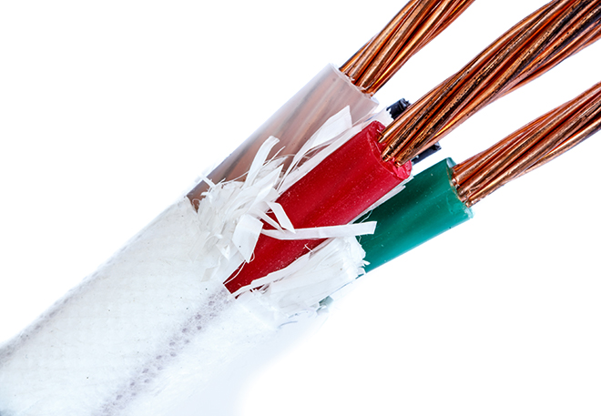
The first part of the charging pathway to consider while attempting to minimizing loses—and one which is entirely under the control of the EV owner—is the size of the wire from the circuit breaker in the load center (aka the breaker box) to either the receptacle which an EVSE plugs into, or to a hard-wired EVSE. OBCs will be considered in more detail in the second part of this article, but suffice it to say that many of the OBCs for EVs in the North American market are equipped to accept either 120 VAC or 240 VAC, and a variety of ampacities.
While charging at 120 VAC might get you out of a jam when away from home, it should otherwise be avoided, both because of the fixed auxiliary and parasitic loads in the EV that can divert an alarmingly high percentage of the OBC’s power output away from actually recharging the battery pack (said loads will be discussed below), and because a 120 VAC circuit is usually supplied by a 20 A breaker, of which only 16 A is “legally” available, for a rather meager 1,920 W.
The aforementioned “legal” restriction is due to a rule found in the electrical subsection of most building codes (e.g. the NEC in the US; the IEC in most other places), which restricts the maximum continuous load on a breaker to 80% of its ampacity—EV charging definitely qualifies as a continuous load. Thus, for a 50 A breaker—as is commonly specified for ovens/ranges and, of course, EVSE outlets—a maximum of 40 A continuous is allowed. The electrical code also dictates the minimum size of the wire (aka its gauge) that must be used between the circuit breaker and the outlet, and this minimum is based primarily on the breaker’s ampacity (and not, as a layperson often assumes, for the stated ampacity of the outlet, though it’s certainly best if the two match!), and on ensuring that the total voltage drop stays under a certain amount (typically 3% maximum). For example, the branch circuit for a 20 A breaker must use 12-gauge wire, minimum, while a circuit supplied by a 50 A breaker must use 6-gauge wire, minimum. Less well appreciated—and even sometimes overlooked by both electricians and building inspectors—is that secondary factor of keeping the voltage drop under 3%, as this effectively requires an increase in wire size over a certain distance. For example, 6-gauge wire might be acceptable to supply a 50 A outlet that is a few meters or tens of feet away from its breaker, but 4-gauge might be needed if the outlet is dozens of meters or more than 100 feet away.
Over a 100-foot run, using #4 wire for both current-carrying conductors will only cost $22 more, but will reduce resistance by 29.3 mΩ, shaving off 47 W of loss at 40 A.
Any competent electrician should be able to size the wire for a Level 2 EVSE in a manner which complies with code, but mere compliance is not necessarily ideal here, particularly if the EVSE or outlet is far away from the breaker, as any losses in the wiring are directly added to the cost of recharging the EV battery. For example, that allowed 3% voltage drop on a 240 VAC nominal circuit is 7.2 VAC, and at 40 A that works out to a loss of 288 W. Given that electricity costs 11-30 cents per kWh across the US (typically around 13 cents/kWh here in central Florida), that 288 W loss will incur an additional cost of 3-9 cents per hour of charging. Of course, the larger wire costs more, and currently a single #6 wire is $1.27 / foot at a major big box retailer, and has a resistance of 0.3951 mΩ / foot, whereas the next larger-size wire, #4, is $1.38 / foot, and has a resistance of 0.2485 mΩ / foot. The additional $0.11 / foot for #4 cuts resistance by 0.1466 mΩ / foot, or about 37%. Over, say, a 100-foot run, using #4 wire for both current-carrying conductors (the neutral, if used, and grounding wire, can be the same size in both cases, so not a factor here) will only cost $22 more, but will reduce resistance by 29.3 mΩ, shaving off 47 W of loss at 40 A. At $0.13/kWh that will take around 3,600 hours to pay back at $0.13 / kWh, which would make no sense for an intermittent load like a dryer or range, but for a Level 2 EVSE (or OBC) used several hours per day the case for the upgrade is compelling.
And what about a Level 1 EVSE or OBC maxing out at 16 A on a 120 VAC circuit? Here the minimum gauge wire required by code is #12, but for an outlet 100 feet away, that technically won’t suffice, because the total loop resistance will then be 0.318 Ω (1.588 mΩ / foot * 2 * 100 feet), resulting in about 5 VAC of drop (~4%) at 16 A, and 81 W of loss. Upsizing to #10 wire would cut the loop resistance to 0.2 Ω, and the loss to 51 W (so less compelling than the Level 2 case), but the big obstacle here is that most 120 VAC receptacles can only accept #12 or #14 wire gauges; #10 or larger simply won’t fit.
A similar rationale applies to the EVSE’s charging cable, except that in this case there is little the owner can do to improve the situation except to locate the outlet (or charger) as close to the charging port on the EV as possible, so that the shortest possible cable can be used (if there is a choice of cable length—often there isn’t).
Perhaps the single biggest contributors to charging losses are the various auxiliary and parasitic loads in the EV, especially for heating or cooling the battery. Li-ion batteries tend to tolerate charging while hot reasonably well, so cooling the pack usually just requires running a coolant circulation pump and a fan on a heat exchanger, which costs a few hundred watts, worst-case. Charging while cold can be downright catastrophic, however, because it can result in a failure referred to colloquially—but accurately—as “lithium plate-out.” This occurs when the lithium ions that are part of the electrolyte salt (the “ion” in Li-ion) come out of solution as a metal by plating onto the anode. When this occurs, battery capacity is permanently reduced, at best, and in severe cases it will short out the cell internally (possibly leading to a fire that only a truckload of sand can extinguish). The rate at which plate-out occurs accelerates rapidly as temperature drops below 5° C or so (depending on the exact solvent mix used for the electrolyte), especially at high charging rates, so heating the battery to keep it above this temperature, at least, is a far more pressing objective (see, for example, the battery problems in cold weather suffered by the first-generation Nissan Leaf, which did not have a pack heater).
Unfortunately, heating a relatively large mass that is also poorly insulated—such as an EV battery pack—can end up consuming far more power than all the other losses in the charging process combined, so it behooves the OEM to strike a careful balance, in order to run the heater only as long as necessary to prevent plate-out and not, say, in some misguided attempt to improve discharge performance as well (ahem…).
When minimizing losses in the charging port interconnects the main issues are corrosion from exposure to humidity, salt, etc, and a loss of contact pressure, either due to wear between the sliding contact surfaces, or metal fatigue, from repeated use.
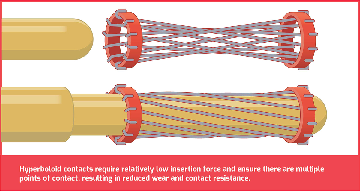
Finally, let’s consider the contact resistances of the various interconnects and terminations in the charging system. The most obvious of these are the charging port plug and receptacle (removable). The less obvious—simply because they are usually hidden from view—are bus bar and high-current cable connections (fixed). Minimizing losses in the fixed interconnects between bus bars and/or terminals is almost entirely the province of the OEM, whereas for the charging ports, the main issues are corrosion from exposure to humidity, salt, etc, and a loss of contact pressure, either due to wear between the sliding contact surfaces, or metal fatigue from repeated use. Corrosion is best prevented at the design stage by selecting sufficiently noble metals for the contacts in the first place (e.g. brass, nickel or nickel-plating, stainless steel, etc), but can be prevented with varying degrees of success by applying a protective coating such as dielectric grease to the receptacle contacts. Metal fatigue—in which springiness is lost over time from repeated flexing—is also best addressed at the design stage by selecting round pins for the plug and so-called “hyperboloid” (more colorfully known as “Chinese finger trap”) contacts for the receptacle, as this combination requires relatively low insertion force, and ensures that there are multiple points of contact, resulting in reduced wear and contact resistance. If a bladed pin and receptacle—such as the NEMA 14-50 “range” outlet mentioned earlier—is being used for charging, just keep in mind that it will wear out much more rapidly—perhaps in as few as 100 insertion/removal cycles—so the pair should be changed on a regular basis to avoid too high an increase in contact resistance over time (all the more reason to go with J1772, CCS, CHAdeMO, etc).
Two things conspicuously absent from the discussion so far are inefficiencies in the OBC and the battery itself. The battery won’t really be covered at all, since most of the Li-ion chemistries already have close to 100% coulometric efficiency, which is the fancy-pants term for the ratio of charge in vs charge out in an electrochemical cell (compared to 50-70% for older chemistries such as lead-acid and Ni-Cd). Consequently, research in battery technology is mainly focused on improving energy density and cycle life, rather than coulometric efficiency per se. OBCs, however, are ripe for more innovation, and due to their much higher complexity relative to the other parts of the charging pathway, they will be the sole focus of part two in this article series.
Read more EV Tech Explained articles.
This article appeared in Issue 57 – Sept/Oct 2021 – Subscribe now.