Word capacitance is derived from capacity, capacity is to contain, or store. a capacitor working principle refers to a storing of electrical energy in the form charge unit of charge is coulombs. Capacitors are available in a very wide range and sizes, but functionally all are used for storage of electrical charge. Here instead of going into details of a specific capacitor, we shall limit ourselves to the general principle and construction of capacitor.
What is a Capacitor?
The capacitor is a device that is capable of storing electric charge +ve and -ve both. Due to this charge, a potential difference gets created between the terminals And a capacitor behaves like a battery.
Construction of a Capacitor
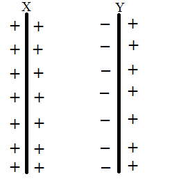
Basically, a capacitor consists of two parallel conductive plates separated by insulating material. Due to this insulation between the conductive plates, the charge/current cannot flow between the plates and is retained at the plates. The plates may be of different shapes like rectangle, square, circular, and can be made into different shapes like a bead, disc, or cylindrical type by always maintaining constant insulation level between the plates. The size of these capacitors depends on their power handling capacity.

Capacitor Symbol

Working Principle of a Capacitor
As we know that when a voltage source is connected to conductor it gets charged say by a value Q. And since the charge is proportional to the voltage applied, thus the basic capacitor working principle is that it stores electrical charge and act as voltage source
Q∝V
In order to equate the charge Q and voltage V.
Q=CV, where C is the capacitance of the conductor.
C=Q/V, the value of C is dependent on various factors as given hereunder.
- The plate/conductor area. Larger the plate area greater is the charge accumulation on it.
- The gap between the plates. With a large gap between the plates, the capacitance gets reduced due to a reduction in charge binding/field force or reduction in permittivity.
- The dielectric medium. The value of capacitance can increase if we use a material with high permittivity. As an example, the relative permittivity of air is approximately= 1, while that of glass/ceramic is approximately more than 7.
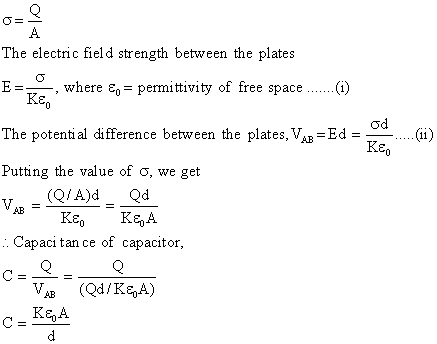
All these factors are of utmost importance while designing a capacitor. The mathematical expression for the same is:
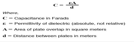
Suppose A be the area of each plate, ‘d” the separation between the plates, K the dielectric constant of medium between the plates.
is the magnitude of charge density of plates, then capacitance of a parallel plate capacitor is as follows.
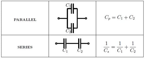
The formula for energy storage in a capacitor is given by Q=CV and W=CV²/2. This is also known as Capacitor Formula. capacitance of a parallel plate capacitor is C1+C2+…….Cn, whereas the capacitance of a series capacitor is given below in the figure.
After removing this battery from this capacitor, these two plates hold positive and negative charge for a certain time. Thus this capacitor acts as a source electrical energy . If two ends (plate I and plate II) are connected to a load, a current will flow through this load from plate-I to plate-II until all charges get vanished from both plates. This time span is known as discharging time of the capacitor.
Capacitor Equations
capacitor charging equation considering the simple RC circuit is given by Q=Q0(1−e−t/CR) If at any time during charging, I is the current through the circuit and Q is the charge on the capacitor. As the current stops flowing when the capacitor is fully charged in principle but actually it is 99.999%, When Q = Q0 (the maximum value of the charge on the capacitor), I = 0.
capacitor discharging equation considering the simple RC circuit is given by Q=Q0e−t/CR where Q0 is the maximum charge at time t=0.
Capacitor in a DC Circuit
Suppose a capacitor is connected across a battery through a switch.
When the switch is ON, i.e., at t = +0, a current will start flowing through this capacitor. After a certain time (i.e. charging time) capacitor never allow current to flow through it further. It is because of the maximum charges is accumulated on both plates and capacitor acts as a source which has a positive end connected to the positive end of the battery and has a negative end connected to the negative end of the battery with the same potency.
Due to zero potential difference between battery and capacitor, no current will flow through it. So, it can be said that initially a capacitor is short-circuited and finally open circuited when it gets connected across a battery or DC source.
Capacitor in an AC Circuit
Suppose a capacitor is connected across an AC source. Consider, at a certain moment of positive half of this alternating voltage, plate-I gets positive polarity and plate-II negative polarity. Just at that moment, plate-I accumulates positive charge and plate-II accumulates negative charge.
But at the negative half of this applied AC voltage, plate-I gets a negative charge and plate-II positive charge. There is no flow of electrons between these two plates due to dielectric placed between the plates but they change their polarity with the change of source polarity. The capacitor plates get charged and discharged alternatively by the AC
Capacitor Application
- In electronics, we use capacitors for filters, oscillators, and tuned circuits, and for these applications mostly ceramic capacitors due to their superior dielectric properties.
- Capacitors can also be used as timing devices as the charging and discharging time can be predetermined using RC time constant.
- Capacitors are used as radio frequency coupling/blocking and decoupling / bypassing devices.
- Capacitors are also used for smoothing device for various wave generators and frequency converters, inverters for example rectifier and are also used where the switching frequency is high.
- Capacitors are used as voltage dividers and multipliers.
- As holding device capacitors are able to retain the voltage/value even if there is an interruption in supply.
- For the protection of various power electronic devices capacitors are used in snubber circuits.
- Capacitors play a significant role in noise filtering. Film type capacitor is suitable for this application.
- All analog to digital converters has capacitors as the most important component. Electrolytic capacitors may be used for this application.
- Various ignition systems also use capacitors for high ignition voltage.
- In an electric system, the capacitor plays an important role in power factor improvement which not only increases the active power but also increases the life of switchgear.
- Capacitors are also used to provide an alternative source of direct current supply (Emergency supply) for tripping in the event of main battery failure.
- Capacitors are also used as phase splitter in single-phase alternating current motor. The aluminum electrolytic capacitor is most suitable for this application.
- Capacitor are also used for a power factor correction
- in an electronic circuit noise is diverted to ground using bypass capacitor which works on the principle of low impedance for high frequency signal.
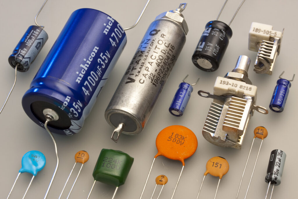
Capacitor Types
1. Fixed Capacitor
As the name indicates, a fixed capacitor is a type of capacitor that produces a fixed amount of capacitance. This means that it is able to store only a predetermined amount of charges in it. Further fixed capacitors can be classified as per the dielectric material used between the conducting plates, for example, paper capacitor, plastic capacitor, ceramic capacitor, etc.
1. Polarized Capacitors
Polarized capacitors are capacitors that have a predefined polarity of the pins. It is essential to keep the polarity of the capacitor pins in mind before connecting a polar capacitor to the circuit. The most common polarized capacitors are electrolytic capacitors.
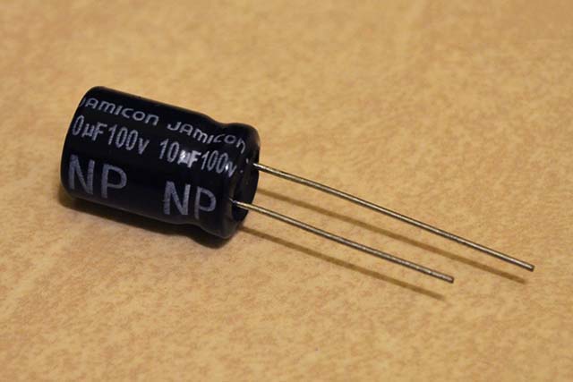
2. Non-Polarized Capacitors
Non-polarized or non-polar capacitors are the capacitors that can be connected in a circuit irrespective of the polarity of the pins. This signifies that the non-polar capacitors do not have any assumed polarity of the pins. They are also known as bipolar capacitors.
2. Variable Capacitors
The capacitors whose value of capacitance can be varied either electronically or mechanically are known as variable capacitors. A variable capacitor consists of a fixed plate and a variable plate. By varying the distance between the two plates, the capacitance can be varied. These capacitors are used in antennas for impedance matching.
1. Tuning Capacitors
The tuning capacitor or the tuning condensers consists of a stator, a rotor, and a frame. The stator is a stationary part, and the rotor moves with the help of a movable shaft. When the rotor blades move into the stator slot, they act like the capacitor plates.
The capacitance value is maximum when the rotor blades fit the slots of the stator, and the capacitance value is minimum when the blades are away from the slots. The capacitance value of tuning capacitors ranges from a few Pico Farads to a few tens of Pico Farads. They are mostly used in the radio receiver LC circuits.

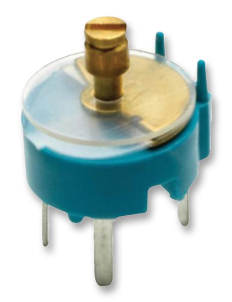
2. Trimmer Capacitors
Trimmer capacitors consist of three pins; one is connected to a stationary plate, one to a rotary plate, and the other one is the common pin. The capacitance of a trimmer capacitor can be varied using a screwdriver. The movable plate of the capacitor is semi-circular in shape. The capacitance depends upon the area opposite the movable semi-circular disk and the fixed plate. When the opposite area is bigger, the capacitance value will be higher, whereas with the reduction in the opposite area, the capacitance decreases accordingly.
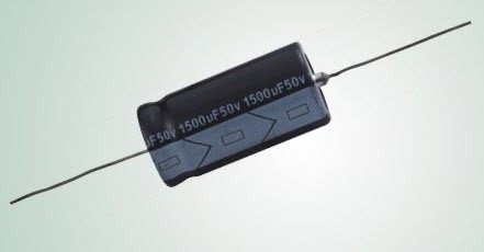
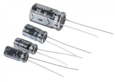
3. Electrolytic Capacitors
The first electrode of an electrolytic capacitor is made up of a thin metal film, whereas the second electrode or the cathode consists of a semi-liquid electrolyte solution, which is in jelly or paste form. A thin layer of oxide gets developed between the two electrodes, which acts as the dielectric medium. An electrolytic capacitor is used in applications where high capacitance values are required.
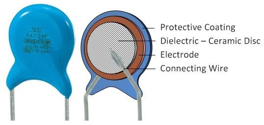
4. Ceramic Capacitor
Ceramic capacitors are the capacitors that make use of ceramic as a dielectric medium between the two electrodes. They typically have a low value of capacitance and are non-polar capacitors. A ceramic capacitor is generally round-shaped and orange in colour.
5. Film Capacitor
The film capacitors make use of plastic film as a dielectric material. They are most commonly used in applications where stability, low inductance, and low price is desirable.
Further, film capacitors can be classified as polyester film, metallized film, polypropylene film, PTE film, and polystyrene film capacitors.
How to Select a Capacitor for circuit design
While designing the power supply we have to choose capacitor and before that capacitor designing is important such that it withstand the worst case condition. here we list down the most important factors that needs to be considered while capacitor selection.
1. Capacitance Value
first thing first, before designing any capacitor for any power supply capacitance should be known and that comes with a proper calculation. method of calculating the capacitance varies from converter to converter.
2. Rated Peak current
rated peak current value is the maximum current that capacitor can tolerate without damage. ripple current value should not be greater than the peak current value.
3. Frequency
frequency of current entering in the capacitor should be known and must not be greater than the rated frequency of the cap and should have atleast 30% margin considering the EMI affect.
4. ESR and ESL
ESR stands for equivalent series resistance and ESL stands for Equivalent series inductance. each capacitor has internal resistance which creates additional power loss and voltage drop to avoid that ESR should be as low as possible. whereas ESL should be avoided which can done by operating the capacitor below that self resonating frequency (SRF) of the capacitor i.e F_srf > F_operating. capacitor behaves as capacitor below SRF and above SRF it act as inductor.
5. Tolerance
Capacitance can vary between minimum and maximum value due to various reason’s. so what we have to look is minimum capacitance worst case should be greater than the calculated one.
6. Temperature
operating temperature should be noted carefully which should be within the range of rated temperature.
7. Dissipation factor
dissipation factor tells that how much is the power loss capacitor will provide. more the less more the good.
8. Type of capacitor
there are many capacitor in the market with same capacitance value, so which one should be chosen, the answer it depends on the application. for eg. electrolytic, ceramic, mica, polyester, film, polypropylene film, thin film capacitor, MLCC, others, example DC high voltage low power with polarity we use electrolytic capacitor.
Summarized
In this article we looked into various aspect of capacitor and explained in the details, we also looked into basic working principle of capacitor along with the circuit equations. after that we looked into various applications where this components can be used and how ? after that we saw how many types of capacitor are there ? and which one should be considered for our application.The most important thing that we looked into is factors affecting the selection of capacitor.